Welcome to Qingdao ACES
- All
- Product Name
- Product Keyword
- Product Model
- Product Summary
- Product Description
- Multi Field Search
Please Choose Your Language


Views: 0 Author: Site Editor Publish Time: 2026-09-30 Origin: Site


A manifold is the central nervous system of any fluid or hydraulic setup. Failure here often stems from hidden micro-porosity, shifting cores, or machining misalignment. These defects result in catastrophic leaks, severe pressure drops, and costly system downtime. Fluid control demands absolute precision. Your system's reliability relies entirely on how well a foundry manages the initial pour and internal geometry.
This guide equips engineering and procurement leaders with an evidence-based framework to evaluate foundry capabilities. You will learn exactly what to verify before approving a production run. We help you ensure the casting manifold parts you source meet strict dimensional and pressure-holding requirements. Foundries often make bold marketing claims. You must look past those claims and demand verifiable quality standards.
By following this guide, you can eliminate structural risks early in the procurement cycle. You will discover practical methods for material selection, flow path validation, and defect prevention. We highlight the exact certifications and testing protocols you need to secure high-performance components.
Material Suitability: Align alloy choices (like bronze or brass) directly with fluid corrosivity and operating pressure requirements.
Core Precision: Internal flow paths dictate performance; demand proof of advanced core-making and shifting prevention.
Casting-to-Machining Alignment: Secondary CNC machining is non-negotiable for sealing surfaces; unified foundry-machining operations reduce defect rates.
Mandatory NDT: Hydrostatic testing and X-ray inspection are baseline requirements to verify the absence of internal porosity.
Selecting the right alloy represents the first critical step in manifold design. You must choose metals based on specific fluid applications, such as water, oil, or harsh chemicals. The ultimate success criteria include high tensile strength, absolute pressure tightness, and long-term corrosion resistance. Fluid system casting parts operate under immense stress. Poor material choices lead to rapid degradation, galling, or sudden rupture.
Engineers frequently evaluate bronze and brass for these applications. You should specify a bronze casting manifold when your application demands excellent corrosion resistance and anti-galling properties. Bronze thrives in marine environments and heavy-duty hydraulics. It withstands saltwater exposure and resists wear from continuous friction. On the other hand, you might assess the viability of a brass casting part for standard commercial plumbing. Brass offers excellent machinability and suits lower-pressure fluid systems perfectly.
You must address the physical realities of sourcing a bronze sand casting part. Engineers must manage the delicate balance between upfront tooling costs, volume scalability, and acceptable surface finish. Sand casting provides great flexibility for large, complex geometries. However, the raw surface finish requires careful secondary processing to meet sealing requirements.
Never rely on a foundry's verbal assurance regarding material grade. You must request Material Test Reports (MTRs) for every batch. MTRs confirm the exact chemical composition and mechanical properties of the poured metal. Review these documents thoroughly before approving any production run.
Alloy Application and Characteristics
Material Type | Primary Advantages | Ideal Applications | Limitations |
|---|---|---|---|
Aluminum Bronze | High tensile strength, anti-galling, excellent corrosion resistance. | Marine hydraulics, heavy industrial fluid control. | Higher raw material cost, harder to machine. |
Standard Brass | Cost-effective, exceptional machinability, good pressure tightness. | Commercial plumbing, low-pressure air/water systems. | Prone to dezincification in aggressive environments. |
Silicon Bronze | Superior weldability, great surface finish potential, moderate strength. | Specialty valves, architectural fluid features. | Lower yield strength compared to aluminum bronze. |
Always align your alloy choice with the specific operating temperature and fluid corrosivity. Require your supplier to perform spectrometer testing on the melt before pouring. This proactive step ensures the chemistry remains within strict industry standards. A minor deviation in tin or zinc content can drastically reduce the pressure-holding capability of your manifold.
Manifolds feature complex, intersecting internal channels. These channels control the fluid direction, pressure, and flow rate. The primary engineering challenge lies in maintaining the integrity of these hidden pathways. Turbulence or pressure drops often stem from poor internal cast surfaces. Misaligned channels also restrict fluid movement and create unwanted backpressure.
You must rigorously evaluate the foundry's sand core technology. Internal cavities require precision sand cores. Ask your suppliers about their specific core-making technology. Shell cores and cold box methods generally yield tighter dimensional accuracy. Ensure complex geometries in a pump manifold part remain smooth and dimensionally precise. Rough internal walls induce cavitation, which slowly destroys the manifold from the inside out.
Preventing core shift is an absolute necessity. During the metal pouring process, liquid alloy exerts immense buoyant forces on the sand cores. If a core shifts even a fraction of a millimeter, it compromises the entire component. Core shifting leads to uneven wall thicknesses. This creates localized weak points prone to bursting under high hydraulic pressure. You must question your foundry on how they secure cores using precision core prints and chaplets.
As a proactive buyer, you should demand flow simulation data during the prototyping phase. Modern foundries use software like MAGMASOFT to predict how molten metal fills the mold. These simulations highlight potential core shift risks and turbulence zones before any metal is poured. Additionally, require physical cross-section validation. Have the foundry slice the first prototype in half. This allows you to visually inspect the internal channel alignment and verify uniform wall thickness.
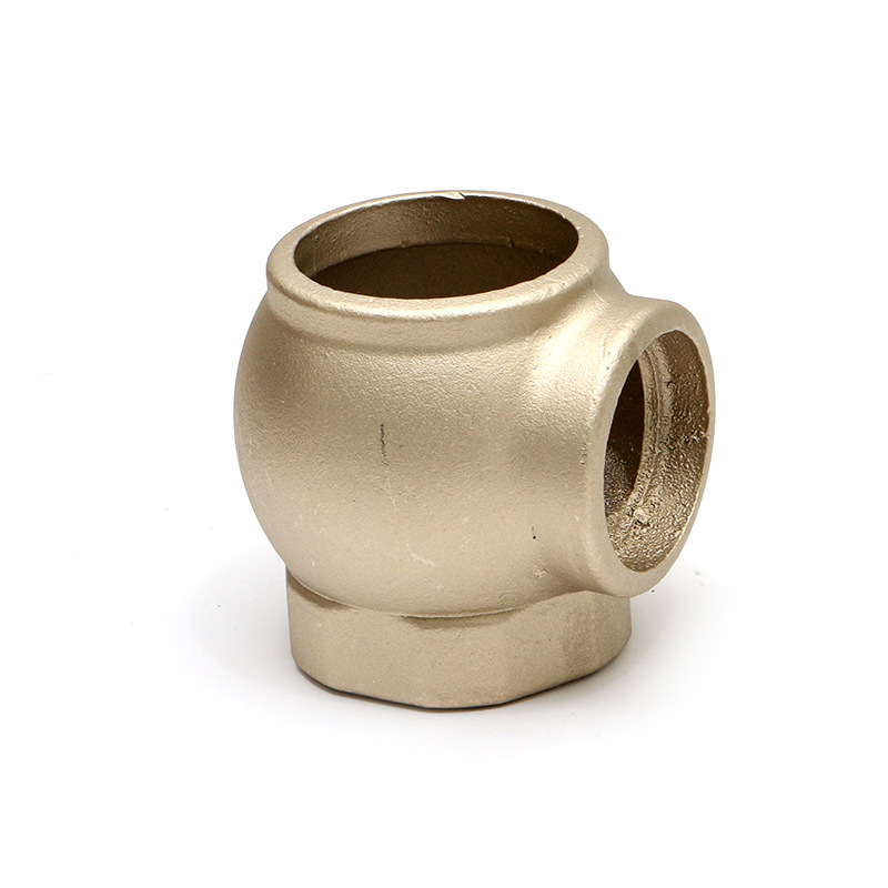
The relationship between the raw casting process and CNC machining dictates the final quality of the manifold. A raw casting simply cannot hold the tight tolerances required for functional fluid control. You need precision CNC machining to create O-ring grooves, threaded ports, and perfectly flat mating faces. Without secondary machining, achieving a leak-free seal is impossible.
You must understand the harsh realities of machining cast metals. Cast surfaces often feature a hardened "skin" containing microscopic sand inclusions. These impurities cause rapid cutting tool wear. Furthermore, aggressive heavy cuts can expose hidden subsurface porosity. A surface that looks solid on the raw casting might reveal pinhole leaks once a CNC machine removes the top layer of metal.
To combat misalignment, you need a strict datum point strategy. The foundry and the machine shop must agree on specific datum points. These reference points ensure external machined features perfectly align with the internal cast flow paths. If the machine shop uses different reference points than the foundry, the threaded ports will not align with the internal channels. This misalignment restricts fluid flow and ruins the manifold.
Sourcing raw castings from one vendor and machining from another invites severe operational risk. If a machined manifold leaks, the machine shop will blame the foundry for hidden porosity. The foundry will blame the machine shop for cutting too deep or clamping the part incorrectly. This finger-pointing delays your production schedule. We strongly recommend sourcing from vendors offering integrated casting and CNC capabilities under one roof. Single-source accountability drastically reduces defect rates and simplifies quality control.
Visual inspection is completely useless for high-pressure manifolds. Internal defects remain the primary failure mode in fluid systems. A part might look flawless on the outside while harboring massive shrinkage cavities near intersecting channels. You must implement a rigorous quality assurance protocol to detect these hidden threats.
A comprehensive Non-Destructive Testing (NDT) protocol is your best defense against catastrophic failure. You should make the following tests mandatory for any critical manifold application.
Radiography (X-Ray/CT): This method remains essential for detecting internal shrinkage and gas porosity. X-rays reveal voids hidden deep within complex internal junctions. You should demand X-ray reports for initial prototypes and periodic production batches.
Hydrostatic Pressure Testing: This serves as the ultimate pass/fail metric. Technicians plug all ports and pressurize the manifold using water or hydraulic fluid. Parts must be tested at 1.5x to 2x their maximum operating pressure. The part must hold this pressure for a specified duration without sweating or leaking.
Dye Penetrant Testing: This technique is highly useful for finding surface-breaking micro-cracks. Technicians apply a fluorescent dye to the machined sealing faces. Under UV light, any microscopic cracks become immediately visible. This ensures your O-ring grooves remain structurally sound.
You must verify the supplier’s QA processes align with relevant industry standards. Look for documented compliance with ASTM or ASME casting specifications. Additionally, ensure the facility holds a valid ISO 9001 certification. An ISO-certified quality management system proves the foundry follows standardized procedures for defect tracking, instrument calibration, and continuous improvement. Do not accept internal foundry standards if they fail to reference recognized global frameworks.
Finding a foundry capable of pouring metal is easy. Finding a strategic partner capable of delivering complex manifolds requires deep evaluation. You must assess scalability and track record early in the discussion. Evaluate if the supplier can scale from initial prototype runs to volume production. Ask them to provide historical data on their scrap rates during volume ramp-ups. A high scrap rate indicates unstable process control.
Engineering support separates average vendors from exceptional partners. A reliable partner for a custom casting manifold will offer Design for Manufacturability (DFM) feedback. They will review your initial designs and suggest minor geometry tweaks. Adding subtle radiuses or adjusting wall transitions can drastically improve feedability and reduce internal porosity. You want a foundry that pushes back on bad designs rather than blindly pouring flawed parts.
To get accurate quotes and assess technical competency, you must submit a comprehensive RFQ (Request for Quote) package. Vague requests yield inaccurate pricing and delayed timelines. Your RFQ package should explicitly include:
Native 3D CAD models clearly showing all machining allowances and draft angles.
Detailed 2D drawings featuring critical tolerances and strict GD&T (Geometric Dimensioning and Tolerancing) callouts.
Exact material specifications, including acceptable alternative alloys.
Comprehensive testing requirements, specifying pressure thresholds for hydrostatic testing and acceptable porosity levels for X-ray inspection.
Providing this level of detail forces the foundry to evaluate your project seriously. It allows their engineers to identify tooling complexities immediately. Clear communication at the RFQ stage prevents costly change orders during production.
Sourcing high-performing manifold castings requires tight control over metallurgy, core design, machining setups, and NDT validation. You must approach procurement as a continuous risk-mitigation process. Evaluating a supplier involves looking deep into their core-making technology and datum control strategies. Integrated foundries offering both casting and CNC machining provide the safest route to consistent quality.
Never compromise on pressure testing or baseline material certifications to save on upfront unit costs. Skipping X-ray inspections or hydrostatic testing inevitably leads to field failures. The expense of replacing a ruptured manifold in the field far exceeds the cost of rigorous upfront quality assurance.
We encourage buyers to submit their manifold drawings for a rigorous DFM review and tooling feasibility assessment. Engage with engineering teams early in your design phase. By collaborating on feedability and core stability, you guarantee a robust, leak-free component that withstands the harshest fluid control environments.
A: The most common cause is internal shrinkage porosity exposed during secondary CNC machining. Voids form inside the raw casting as the metal cools and contracts. When the machine shop cuts away the outer layer to create a port or sealing face, they expose these hidden voids. This creates an immediate path for high-pressure fluid to escape.
A: Your choice depends on size, volume, and internal complexity. Sand casting remains the standard for larger, heavily cored parts. It handles massive intersecting channels cost-effectively. Investment casting is better suited for smaller manifolds requiring exceptional surface finishes and incredibly tight as-cast tolerances without extensive secondary machining.
A: Foundries maintain wall thickness using precision core prints, chaplets, and robust tooling design. Core prints securely anchor the sand core within the mold cavity. Chaplets provide internal metal supports to prevent the core from bowing or shifting during the metal pour. This precise positioning prevents uneven walls.


