Welcome to Qingdao ACES
- All
- Product Name
- Product Keyword
- Product Model
- Product Summary
- Product Description
- Multi Field Search
Please Choose Your Language


Views: 0 Author: Site Editor Publish Time: 2026-09-22 Origin: Site


Manufacturers often view Sand casting as a historic metalworking process. However, it remains a highly strategic manufacturing decision today. The process balances tooling costs, production volumes, and part complexity perfectly. Procurement teams and engineers constantly evaluate this method against other alternatives. They weigh it directly against die casting, investment casting, and CNC machining. Choosing the wrong manufacturing process can derail your budget and production timeline. This comprehensive guide breaks down the exact mechanics of the process. We will explore its commercial viability across different industrial applications. You will learn how to determine if it is the right process for your specific production run. We also cover critical design constraints and supplier selection logic. Readers will gain actionable insights for their next metal procurement project.
Cost-Efficiency at Low/Medium Volumes: Sand casting offers significantly lower upfront tooling costs compared to die casting, making it ideal for short runs and prototyping.
Size and Geometry Flexibility: It is one of the few processes capable of producing massive, heavy components with complex internal cavities using sand cores.
Trade-offs in Precision: While highly versatile, sand casting yields rougher surface finishes and wider dimensional tolerances, typically requiring secondary machining for critical mating surfaces.
Material Versatility: Compatible with nearly all commercially viable metal alloys, including cast iron, steel, aluminum, and bronze.
Modern manufacturing demands strict budget controls. Teams face a massive hurdle when producing complex metal parts. Hardened steel molds for die casting easily exceed $50,000 in tooling costs. This immense capital expenditure destroys profit margins on smaller production runs. Engineers must find a reliable alternative to avoid these staggering upfront costs. This dilemma highlights the exact business problem this specific casting method solves. You can bypass massive investments while still achieving complex part geometries.
Every manufacturing process has an ideal production volume. We call this the "sweet spot." For this method, the volume typically ranges from 1 to 10,000 units annually. Tooling amortization makes absolute sense within this bracket. You spread a much smaller tooling cost across a moderate number of parts. Producing a few dozen prototypes becomes financially viable. Simultaneously, scaling up to a few thousand units remains highly efficient before die casting becomes necessary.
Decision-makers must weigh cost against quality thresholds. You benefit from a significantly lower initial capital expenditure (CapEx). However, you must accept a higher per-part piece price at scale. Secondary finishing requirements also influence the final budget. The raw cast parts feature a rougher surface. They require secondary machining on critical mating surfaces. You must calculate these extra machining costs when evaluating your overall production budget.
Speed to market represents another massive commercial advantage. Foundries produce physical patterns from wood or tooling board rapidly. They can complete these patterns in days. Permanent metal molds take many weeks or even months to manufacture. Furthermore, you can modify these non-metal patterns easily. If an engineering revision occurs, workers simply add or remove material from the existing pattern. This flexibility aids rapid iteration during the product development cycle.
Understanding the exact mechanics helps engineers design better parts. The workflow involves several distinct phases. Each phase requires specific expertise and careful environmental control.
The process begins by creating a physical replica of the final part. Industry professionals call this replica a pattern. Foundries construct patterns using wood, high-density plastic, or metal. Wood serves well for low-volume prototypes. Plastic or polyurethane offers better durability for medium runs. Metal patterns withstand thousands of cycles for higher volumes.
Design for Manufacturing (DFM) fundamentals play a crucial role here. Engineers must include draft angles on the pattern vertical walls. Draft angles allow workers to pull the pattern out of the mold easily. Without draft, the mold walls would collapse. Designers also incorporate shrinkage allowances. Molten metal shrinks as it cools. The pattern must be slightly larger than the final desired component to compensate.
Foundries press a specialized mixture around the pattern to form the mold cavity. They primarily use two distinct types of mixtures.
Green Sand: This is the most cost-effective option. It consists of sand, clay, and moisture. The term "green" refers to the moisture content, not the color. Foundries easily reclaim and reuse this mixture.
Resin/No-Bake Sand: This alternative uses chemical binders instead of clay and water. The binders cure at room temperature. This method yields tighter tolerances. It provides better structural integrity for massive, heavy parts.
Many parts require hollow internal cavities. Foundries use consumable sand cores to form these voids. Workers pack resin-coated sand into a separate core box. They place the hardened core inside the main mold cavity before pouring. The molten metal flows around the core.
Once the mold is closed, the pouring phase begins. Workers pour molten metal into a gating system. The gating system is a network of channels. It controls the speed and turbulence of the metal flow. Proper gating prevents mold erosion and minimizes trapped air.
Riser systems play a critical role during solidification. As the metal transitions from liquid to solid, it shrinks in volume. Risers act as localized reservoirs of extra molten metal. They feed liquid material back into the casting as it cools. This mechanism mitigates shrinkage porosity within the final part.
The metal cools and solidifies completely. Workers then destroy the mold to retrieve the rough part. The industry refers to this step as the shakeout phase. Vibratory tables help separate the loose material from the solid metal.
The raw part still has the gating and risers attached. Fettling is the labor-intensive process of cutting these excess pieces off. Operators use saws, grinders, or plasma cutters for this task. Finally, the part undergoes shot blasting. High-velocity abrasive media blasts the surface. This step removes any burnt-on residue and improves the overall surface finish.
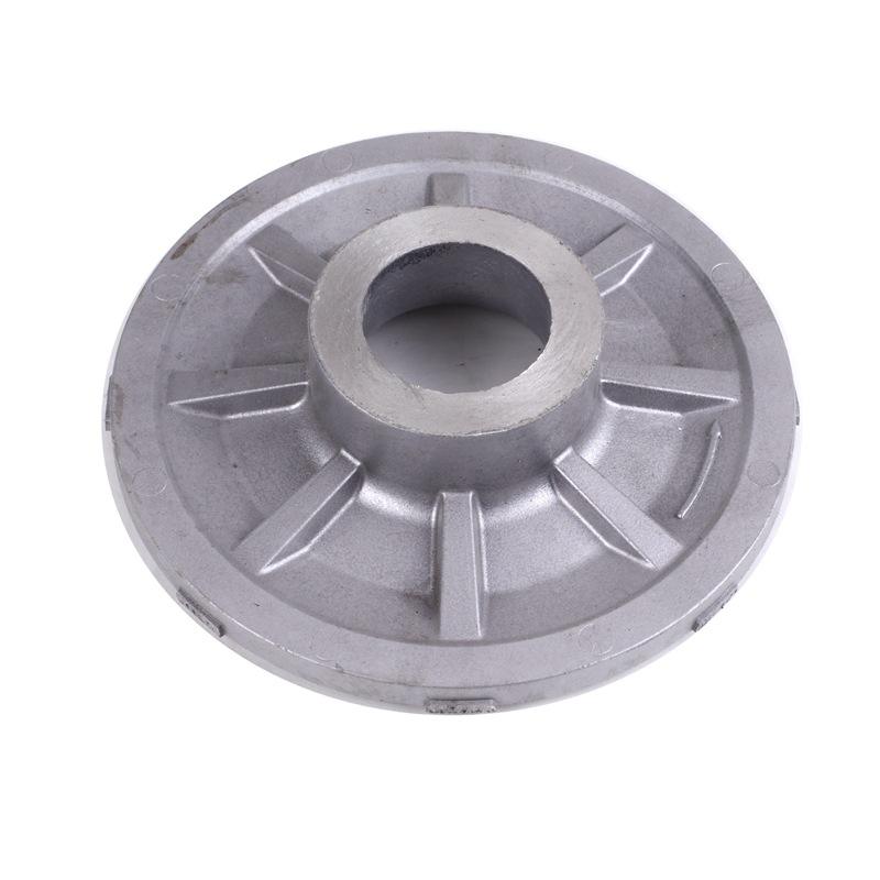
Procurement professionals rarely evaluate one manufacturing process in isolation. You must compare competing methods to ensure commercial viability. Each process offers unique advantages regarding scale, precision, and initial investment.
Die casting dominates high-volume production. It utilizes massive hydraulic presses and expensive steel molds. You pay a massive premium for the initial tooling. However, the piece price drops dramatically at high volumes (e.g., 50,000+ units). Die casting delivers exceptional surface finishes and tight dimensional accuracy straight from the mold.
Conversely, our primary method wins heavily on tooling costs. You spend thousands instead of tens of thousands. It also accommodates much larger part geometries. Die casting machines have strict physical size limits. You can pour virtually any size component using temporary molds.
Investment casting relies on consumable wax patterns and ceramic shells. It produces incredibly precise parts with outstanding surface finishes. This precision often eliminates the need for secondary machining entirely. However, investment casting carries a significant premium price per part. The multi-step ceramic shelling process is highly labor-intensive.
You justify investment casting when machining costs are prohibitively expensive. You also use it for hard-to-machine superalloys. Size limitations present a major difference. Investment casting struggles with massive, heavy components. Temporary sand molds handle enormous parts, such as industrial pump housings and large engine blocks, with ease.
Machining complex parts from solid metal blocks (billets) creates a specific problem. It generates massive amounts of scrap material. The aerospace industry calls this the buy-to-fly ratio. A high ratio means you buy a lot of raw material only to machine most of it away.
Casting solves this problem by producing a near-net shape. You only machine the critical mating surfaces. This drastically reduces CNC machining cycle times. It lowers raw material waste. For complex geometries, casting a near-net shape is vastly more efficient than carving it from a solid block.
Table: Manufacturing Process Comparison
Process Feature | Sand Process | Die Process | Investment Process | CNC Machining |
|---|---|---|---|---|
Tooling Cost | Low to Medium | Very High | Medium to High | None (Fixture only) |
Ideal Volume | 1 - 10,000 | 10,000+ | 100 - 10,000 | 1 - 500 |
Surface Finish | Rough (Requires finishing) | Excellent | Outstanding | Perfect (Machined) |
Size Capability | Very Large | Small to Medium | Small | Machine dependent |
Designing for this specific manufacturing method requires a distinct engineering mindset. You cannot simply apply sheet metal or CNC rules to poured metals. You must respect fundamental thermal dynamics and material properties.
This process accommodates nearly all commercially viable metal alloys. Foundries routinely pour ferrous metals like ductile iron, gray iron, and carbon steel. Ductile iron offers incredible strength for heavy machinery components. Gray iron provides excellent vibration damping for machine tool bases.
Non-ferrous metals are equally popular. Foundries pour aluminum, brass, and bronze daily. Producing an aluminum alloy motor cover requires different thermal considerations than a heavy cast iron engine block. Aluminum cools faster and requires specific gating designs to prevent premature freezing. Bronze offers excellent corrosion resistance for marine applications.
You must establish realistic baseline tolerances early in the design phase. Do not expect CNC-level precision straight from the mold. The industry standard typically aligns with ISO 8062 CT10-CT12 tolerance grades. The exact tolerance depends on the part size and the specific binder system used.
Because of this variation, engineers must add "machining stock." This means you intentionally design critical dimensions to be slightly thicker than the final blueprint. A CNC mill or lathe will later remove this extra stock to achieve tight geometric tolerances. Failing to add adequate machining stock is a common design mistake. It results in scrapped parts during the secondary finishing phase.
Wall thickness rules are non-negotiable. Molten metal loses heat rapidly as it touches the mold walls. If a wall is too thin, the metal freezes before filling the cavity completely. This defect is called a misrun. Depending on the alloy, absolute minimum wall thicknesses range between 3mm and 5mm.
Uniform transitions represent another critical geometry rule. You must avoid abrupt changes between thick and thin cross-sections. Thick sections hold heat much longer than thin sections. As the thin section freezes, it cuts off the liquid feed to the thick section. The thick section then shrinks without a liquid metal supply. This creates internal shrinkage cavities. Always use generous radii and gradual tapers to connect varying wall thicknesses.
Designing sharp 90-degree internal corners (always use fillets).
Isolating heavy metal sections without riser access.
Ignoring draft angles on deep vertical pockets.
Placing critical cosmetic faces at the top of the mold (impurities float upward).
Transitioning from a digital CAD file to physical metal carries inherent risks. Poor foundry selection guarantees project delays and budget overruns. You must know what defects to look for and how to audit potential suppliers rigorously.
Even well-designed parts can fail if the foundry lacks process control. You must monitor three primary defects during your First Article Inspection (FAI).
Gas Porosity: Trapped air or moisture creates spherical holes inside the metal. Proper mold venting and moisture control prevent this.
Shrinkage Cavities: Irregular voids form when liquid metal fails to feed shrinking areas. Better riser placement solves this issue.
Sand Inclusions: Loose sand breaks off the mold wall and embeds into the final part. This ruins cutting tools during secondary machining.
A competent foundry mitigates these risks long before the first pour. They use advanced flow simulation software, such as Magmasoft. This software simulates the exact thermal dynamics of the pouring process. It allows engineers to optimize the gating and riser designs virtually, eliminating trial-and-error guesswork.
Do not select a foundry based on price alone. You must evaluate their Quality Assurance (QA) capabilities. Request proof of their Non-Destructive Testing (NDT) capabilities. NDT allows technicians to look inside the metal without destroying the part. Essential NDT methods include X-ray (radiography), ultrasonic testing, and magnetic particle inspection.
Material certification is equally critical. You must guarantee the structural integrity of your chosen alloy. Ask if the foundry uses a spectrometer. A spectrometer analyzes the precise chemical composition of every metal batch before pouring. Finally, verify their ISO compliance. ISO 9001 certification demonstrates a baseline commitment to repeatable process control.
When you are ready to engage suppliers, prepare a comprehensive Request for Quote (RFQ) package. Incomplete RFQs lead to inaccurate pricing and hidden fees later. Your package must include complete 3D CAD models (STEP or IGES format). It must also include 2D PDF drawings. The 2D drawings should clearly highlight critical tolerances, datum structures, and required surface finishes.
State your material specifications explicitly. Do not just say "aluminum." Specify the exact grade (e.g., A356-T6). Finally, clearly define your Estimated Annual Usage (EAU). Foundries need accurate volume projections to quote the most appropriate tooling material. A wood pattern quote looks attractive initially, but it will fail if your true EAU exceeds 5,000 units.
This manufacturing method remains incredibly relevant in modern supply chains. It serves as a highly strategic choice for large, heavy components. It also dominates mid-volume production scenarios where expensive die tooling is simply cost-prohibitive. By understanding the core mechanics, you can leverage its unique geometry flexibility while mitigating precision trade-offs.
Your immediate next step should be proactive engagement. Do not finalize your engineering drawings in a vacuum. Encourage your purchasing and engineering teams to engage a foundry early in the design phase. A collaborative DFM review will optimize the pattern design, dramatically reduce defect risks, and finalize your true production costs before you commit capital.
A: Lead times generally range from 4 to 8 weeks for a new project. Pattern creation takes 1 to 3 weeks. Pouring and finishing the First Article Inspection (FAI) sample takes another 2 to 3 weeks. Production runs begin only after you approve the FAI sample.
A: A pattern's lifespan depends entirely on its material. Softwood patterns typically degrade after 100 to 500 molds. Polyurethane or high-density plastic patterns routinely last for 5,000 to 10,000 cycles. Machined aluminum metal patterns can easily withstand 50,000 or more cycles without losing dimensional accuracy.
A: There are strict limitations. Unlike die casting, this process struggles with extremely thin walls due to premature metal freezing. Typically, 3mm to 5mm is the absolute minimum wall thickness. The exact limit depends heavily on the specific metal alloy and the localized gating design.
A: The physical mold cavity is completely destroyed during the shakeout phase to extract the final metal part. However, the green sand material itself is highly reusable. Foundries routinely reclaim, sift, re-moisturize, and recycle the loose mixture to form brand new molds daily.


